Thursday, June 27, 2013

Aero Design Progress 2014

Earlier this summer, I did a lap time simulation study earlier this summer to understand the sensitivity of lap time on a number of parameters (including mass, power, downforce, drag, and mechanical grip).  The results of the lap simulation showed mechanical grip to be the most important parameter, followed by downforce and then mass.  Since there is a limit as to what can be achieved with mechanical grip, past those limits aero is still the biggest enabler for decreasing lap times.


Setting goals can be a difficult with a brand new car since there is limited background.  Starting from DWAIT/OD-13, which was around 380-400lbf of downforce at 60mph, I wanted to try and get to ~550lbf at the same speed.  Unrealistic?  Looking back, probably since we're shorter and narrower.

The first set of CFD runs was somewhere around the 360lbf range, with ~35% front.  The first few changes were to get the front wing to produce more downforce for better balance, by making the span of each of the front wing halves larger.  This pushes the inside endplate closer to the body, reducing bypass flow that feeds the diffuser and rear wing.  However, CFD has showed this to be relatively insignificant as long as a reasonable gap is maintained, with a net gain in both downforce and balance.

That got us to around 380lbf, ~40% front.  Most of the work since then has been on the diffuser.  I'll talk about each part of the diffuser separately, though they all do interact in reality.
  • Side tunnels profile: The maximum angle before flow separation starts to occur is ~15 degrees, much like what literature suggests.  However, using a smooth transition into the diffuser and a more airfoil-like profile, we can go to an overall angle of 21 degrees.  However, this is heavily dependent on how well the rear wing is driving the diffuser.
  • Side tunnel exit location: Originally for tunnel volume I wanted the tunnel to exit as far rearward as possible.  I found however that having the diffuser under the "shadow" of the wing in planview was inefficient - the low pressure region from the rear wing was creating a significant amount of lift on that top diffuser surface.  Furthermore, with the airfoil type design on the side tunnel, I can get similar volume at a larger angle and have it exit near the leading edge of the rear wing.  This still resides in the low pressure region from the rear wing, which has the added benefit of allowing suspension points of moving forward, which enables us to get rid of the rear box completely
  • Center tunnel: I thought that having the side walls flare out would create more downforce by creating a larger diffuser volume, but it turns out that extra planview area under the rear wing pretty much negates that gain.  Having a longer center tunnel creates the same issue, and thus the center tunnel is short and steep (15 degrees).  This is a good thing for packaging the jacking bar and its supporting structure.
  • Secondary tunnels: due to the packaging of the frame and engine, secondary tunnels are a way to get a little bit more downforce.  I tried exiting them out at the rear with the center tunnel, at the same point as the side tunnel, and in between.  I think the forward exit is overall the best option.
  • Top side flow: Because of the height of the diffuser and the height of the suspension in front of it, there's not a good way to transition from front closeout panel to diffuser.  I noticed that originally the nozzle on the front side of the diffuser was hurting downforce, as well as the low pressure region on the top side of the diffuser.  By opening the top side to ambient flow, we eliminate both these sources of lift.
Flow above diffuser

Diffuser under surface plot
Pressure plot at diffuser side tunnel plane
Diffuser air flow

With these changes, I've been able to double the amount of downforce the diffuser produces, from 60 to ~130lbf @ 60mph.  This is actually only a little more than last year's diffuser, though I'm not sure how good last year's number actually is - we have a lot more fidelity in CFD now than we used to.

With these few changes, we were up to ~450lbf downforce, ~43% front now.  Close, but not quite there yet.

From this diffuser optimization, we needed to do two things: increase downforce and shift the balance forward.  What is the actual balance required?  I'd think anywhere between 45-48% front is acceptable, considering the low speeds the car encounters since yaw stability will not be much of an issue unless we push the bias to ridiculous levels.  In an autocross car, I tend to think the extra front bias is a good thing.

The next steps were to increase the width of the aero.  We had originally used 52", using a 46" track and 6" tread width.  However, the section with of the tire is 8.5" when mounted on a 7" rim, allowing for an extra couple of inches of aero width.  Finally, to push the balance forward (and increase downforce), we lowered the front wing half an inch so that the endplate sits 2" above the ground now.  This change still requires a little bit of vetting to make sure that the endplate won't hit the ground under normal circumstances (particularly pitch change).


These changes have us just over 500lbf of downforce, 48% front, with an overall L/D of ~2.6.  I think this is about all we can extract from a car this size - and with our targeted 70whp, this puts top speed somewhere around 78mph. This is about 20% more drag than last year, but also 25-30% more downforce.  At these levels of downforce, any additional downforce tends to be very inefficient.

Rear wing airflow 

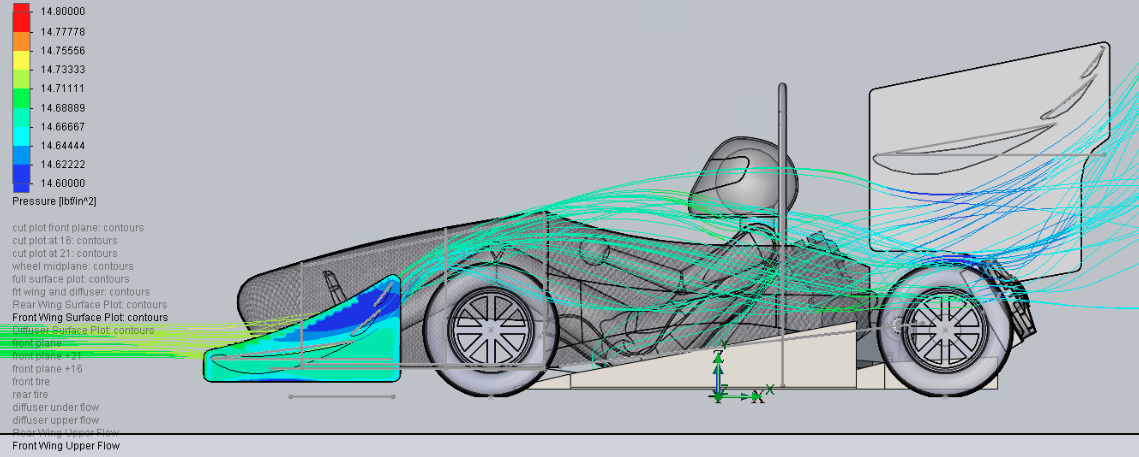
Front wing airflow - note the interaction with the rear wing
Tire airflow is something we may look at in the future as a drag reduction opportunity.  Though tires are never easy, there might be possible improvement in tire drag by injecting momentum into the flow behind the tires.


Monday, June 17, 2013

2014 Architecture

After about 3 weeks, we have a basic vehicle architecture for 2014.  This has been a pretty intense period, as three weeks ago the car was a blank assembly.

The highlights:

  • 10 inch wheels - affects packaging for WHUBs, suspension, and frame primarily
  • Narrower track (~46", front and rear)
  • Smaller wheelbase (60")
  • Complete frame redesign - no rear box
  • Lower occupant positioning - CG focused
  • Lots of downforce
Once again, the focus will be on mass, aero, and mechanical grip.  All of these need to be understood on at least a high level to design an architecture, as many of these enablers and decisions will drive packaging.  For example, originally I started with a rear box because I thought diffuser design would dictat my suspension points, but with CFD I've found that I can actually get better downforce with a shorter diffuser (more on why that is in another post).

So let's take a walk through how to set up an architecture:
  1. Pick your basic dimensions, such as wheelbase, track, overall width, etc.  Go into these decisions knowing that certain design requirements or trade-offs might forces these dimensions to change.
  2. Place components that are "architectural" - the components that will be in the same general vicinity no matter what.  These part include the engine, wheels/tires, driver, basic frame planes (roll hoops, bulkheads), fuel tank volume, etc.
  3. Create a vehicle layout - I tend to do this using typical sections.  Using these sections, I can throw in background and find out what the constraints are for the system, and keep track of these constraints.  That's why in a lot of my models (especially early on) you'll see sketches all over the place.
    • For example place the two sprockets, and from that minimum dimension try to match the rear wheel centerline with the drivetrain axis to minimize driveshaft angle.  This might dictate engine packaging (in our case it does - it forces the engine forward to a certain position), and understanding what compromises this drives is critical.
    • From the example above, the engine more or less defines occupant positioning as well fore-aft in vehicle.  In our case, we actually push the driver farther forward, and with lowering the driver, the car gets longer.  However, this is a tradeoff between yaw inertia and CG that can be quantified and balanced.
  4. Knowing where your hard points are, start throwing in the rest of the background (aero, frame sketches, rough bodywork, radiator, exhaust, etc).  I think it's important to have as many parts as you know will be on the car as possible as early as possible - as familiar as even I am with FSAE cars, I've definitely been guilty of forgetting important constraints.  These parts don't have to be in the right place, just the right vicinity.
  5. With this background, start thinking about where your hard points can be.chosen.  This is important especially for suspension design.  Even in the previous point, you should have a basic idea at least of where your hard points are going to be, but at this point it makes sense to do an initial suspension design and put those points back into the assembly and iterate.  For example, my first suspension design had the frame well into the engine.
  6. In our case, we have the extra step of aero.  We have to have basic definition of where our wings and diffuser are going to be, and how big they're going to be.  Early CFD will tell you at least which concepts are viable, what makes sense, and what doesn't.  Since massive aero is a huge enabler for lap times, I have extra allowances in terms of trade-offs when it comes to aero... many aero enablers drive decisions in other areas
  7. Set your hard points - suspension, frame, aero, etc.  Suspension tends to take precedence here, as packaging is not always easy due to link angles, intereferences, load paths, etc.  However, you still have to work around the frame, which has to work around other architectural parts such as the engine, template rules, the driver, and aero.  There are a lot of suspension components - a-arms, toe links, pushrods, shocks, bellcranks, and ARBs,.  Make sure you have a reasonable motion ratio too at this point - motion ratio linearity may affect packaging as well at this point.
  8. Start working out the smaller details.  Most of these are simply feasibility checks.  A big one for us this year was simply "Can I package WHUBS and suspension in the smaller rim?" and "Can we make the brake balance work with smaller front rotors?".  We choose an exhaust take-down direction, intake concept, radiator placement, make sure the drivetrain works, make sure we have a load path for the jacking bar, start figuring out where to put electrical components, and get all the driver ergo items like shifter and steering wheel in.  A lot of crayon drawings come into play here, and once again it's just carving out space so that everyone knows what space that set of components will take up so that we can check for intereferences.
  9. There will likely be a lot of churn at this point.  Things will change, trade-offs will have to be made, and people will have to rework their previous work.  This is why I advocate nothing more than crayon drawings at this point.  For example, for us this year, it was about two weeks in when we went from a rear substructure to no rear box at all.
  10. At some pont, once you've made sure all the parts of the car are feasible and you have a good strategy and line of sight to the final product, I would call the architecture design finished.  At this point, it's time to delve into detailed design, knowing full well that this detailed design will likely bring up issues that might affect the architecture.  However, hopefully these will be minor changes, and enough due diligence was performed when setting up the architecture that things can move quickly and efficiently from this point forward.
  11. With an architecture set, it's a lot easier now to do design in parallel teams because now you have a bounded problem with well thought out constraints.
Obviously this is a very high level overview, and there's a lot of work that goes on between the lines.  Decisions are made every day, hopefully with data, and communication between the team is key to make sure all involved parties are 1) aware of what's going on and 2) able to offer their perspective on this decision.

Sunday, June 9, 2013

Recap of 2013 Motorsports Car: Intake

I must say that I still haven't full recovered from the tornado that was the month prior to competition, which is why I haven't had the opportunity to update the blog. However, we did take a lot of pictures of the design and fabrication processes, so I would like to go through all of the progress we made as a team building our car, named OD-13.

Just a quick note: I apologize for any redundancy regarding the pics that may occur...I just want to make sure I cover everything, because there is a large gap in the blog.

I'll start with the intake:


This past year, we had a lot of trouble with the intake system. For some reason, the epoxy we were using would sometimes cause small imperfections, and then when we placed the entire intake under vacuum, those weak spots would cave in and case us to remake the intake (about 4 times total).

For the runners themselves, we stuck with carbon fiber because of the large radius of curvature and focus on lightweight design. In order to successfully do this, we had to use wax molds that we wrapped in carbon fiber, and then melted the wax out (we're looking to refine this process for next year).
The molds full of wax

Mmm tasty
 Once we got the hardened wax molds separated from the rapid prototyped molds, we wrapped them with 3 layers of carbon fiber and vacuumed bagged the entire set. It was at this point that we realized the intake plenum had a weak spot right in the middle, as it imploded under 25 inHg, which is wasn't acceptable.

Runners: Good! Plenum: Not so good...

 We redesigned the substructure so that it would have support at the points where it needed it the most, which basically had another structure in the middle. This was still a very lightweight, but sturdy option for us instead of adding extra layers of carbon fiber and epoxy.


New plenum support substructure

 At this point, we had a new plenum, new diffuser, and new runners, so we were ready to put it all together and seal it completely. We aligned everything, applied carbon fiber and epoxy, crossed our fingers, and pulled around 28 inHg of vacuum to simulate the worst case scenario from an engine loading perspective. Everything turned out great! No deflections, no weak spots, and we had an extremely stiff, but lightweight composite intake assembly.


 Once we had the intake, we then needed to machine fuel injector bungs and place them properly on the runners. Our design thought was to mount the injectors close to the intake ports so that the fuel would not compromise the structural integrity of the runners (we noticed that it weakened the runners over time due to large amount of exposure to the race fuel).

Aligning the injector bungs and the mounting structure

Final adjustments

 Once we got everything secured and sealed, the final product was ready to mount on the car!


Finished intake assembly


 Stay tuned for more updates...didn't want to put too many things on one blog post!


Friday, June 7, 2013

Suspension packaging

The great thing about a brand new design is the design latitude.  The bad thing about a brand new design is... the design latitude. Making everything fit properly is never an easy task, and often requires you to take a step back and look for some very creative options.

With the help of susprog, I think I've finished the first iteration of the suspension packaging. 

The front was relatively easy - I was able to get the motion ratios required and the ARB packaging with pullrods without too much issue.
 The rear on the other hand is much more difficult because of the addition of a driveshaft, frame limitations, aero limitations, and rim clearance.  However, everything fits, the min clearance at static is slightly less than 0.1" (cutting it close, I know), so a lot of the success of this design relies on good tolerances and properly jigging parts during construction.


Saturday, June 1, 2013

Design Progress


 Design is moving along at lightning pace right now, with the whole team contributing now.  With lapsim analysis we've been able to figure out what to focus on for this year - the main goals are (in order) to 1) improve grip, 2) improve aero, and 3) reduce mass.  We might be shooting for a narrower width as well due to the nature of the Michigan course, but not sure if a narrower track is worth the reduction in aero area.

A lot of goals 1 and 3 will be accomplished via the 10" Hoosier LC0's (we think - tire data analysis is currently ongoing to verify).  Also, we're looking for significant reduction in CG via driver positioning and packaging optimization.  Weight reduction is looking for a lot of creative design, better analysis to enable less over-design, better CAD accounting for mass, and better manufacturing methods.  CFD analysis has just started today to optimize the aero package for this car, so there's lots of work to do still on that front.

Some teaser shots of what the car might look like next year: